|
||||||||||||||||||

|
I suggest that when you come to fit the drivers that you lay the speakers on their backs and, if you have a nice finish to preserve, place a towel or sheets on the fronts so that you can rest the drivers safely while soldering etc.
Fitting drivers with the cabinets in an upright position can also be awkward because of the back-heavy nature of drivers.
Remember, the drivers should be matched with the same crossover that they were calibrated with. So, make sure that the numbers marked on the drivers (both the tweeter and woofer) match up with the number marked on the crossover that they will be attached to.
Fitting the Tweeter
The tweeter, as well as the woofer, must be sealed in place so that no air can enter or exit through their slot. Enter the Blu-Tack again.I began by cutting some 3mm strips of Blu-Tack and then pushing these strips around the edge of the tweeter slot. I figured that 3mm would be just enough to allow the mass of Blu-Tack to collapse nicely under the tweeter's outer surround to create a good seal and also to allow the tweeter to be tightened to be pretty much flush with the cabinet itself.
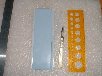 The Blu-Tack is cut into 3mm wide strips |
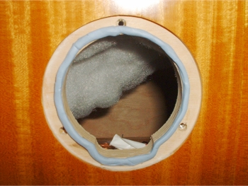 Lay the Blu-Tack around the openning of the tweeter's cut-out |
One strip was not quite enough to complete the surround so a join was necessary. When joining, make sure that the pieces are as thick, and as high as each other (a good reason to make a few at a time for consistency) and that no gaps exist.
I found out later that it was best to smooth down the Blu-Tack a little by hand because with the outer part of the tweeter being plastic, screwing alone would not be enough to completely flatten the assembly down.
The hardest part about this turned out to be the fact that the Blu-Tack prefferred to stick to me than the cabinet but eventually it will stick as required - you just need to persevere.
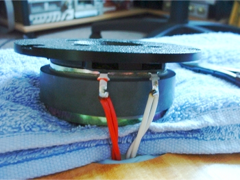 The HF leads have been soldered to the tweeter and trimmed |
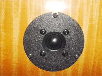 The tweeter fitting is now complete |
I fitted the pre-tinned leads through the holes in the tweeter's terminals from the back (i.e. from the body side) so that I would not have the ends facing the tweeter body. To do this, I had to bend the terminals out slightly - bending them back again once the wires were through. You must make sure that once soldered and trimmed, the terminals will fit through the slots OK. Also make sure that there is no stray solder or wire that could short to the tweeter's body or magnet assembly. To make doubly sure, you could always put a layer of insulation tape on the magnet behind the terminals.
Make sure that you observe correct polarity - the red wire goes to the red terminal.
As you can see from the pictures, I placed a towel above the tweeter - it may also be a good idea to put one below too because you are wielding a soldering iron and you could accidentally drop some solder (or even a tool) onto a precious cabinet finish!
When putting the tweeter through its slot, make sure that none of the Blu-Tack is disturbed so as to compromise the effectiveness of the seal.
Finger-tighten all of the screws to about the same height before turning each with the screwdriver one-after-another in an attempt to tighten them round evenly - thus applying an even spread of pressure to the Blu-Tack underneath to aid with the seal. Do not over-tighten but try to 'feel' that each screw has the same tightness to it.
Fitting the Woofer
Again, we go through the sealing process. I used exactly the same method for this that I did with the tweeter - 3mm wide strips of Blu-Tack around the woofer hole.
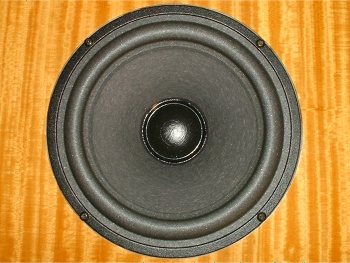
 Blu-Tack applied to the inner rim of the woofer slot |
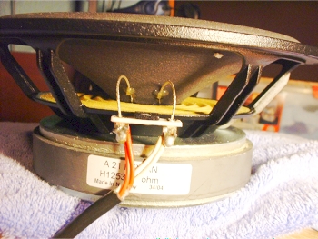 The woofer has now been soldered to the LF lead |
I rested the woofer at the top of the cabinet (i.e. on top of the tweeter) to solder. Bear in mind that he woofer will be rotated to keep the lead at the top of the cabinet so that we can drape the remaining wadding over it...
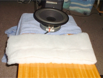 First, fold the wadding in half |
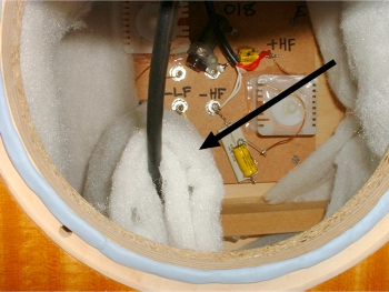 Drape the folded wadding over the LF lead |
So, we have draped the folded wadding over the LF lead. Bear in mind that this will move slightly when fitting the woofer into place. It should be allowed to fall slightly but shouldn't be long enough to obscure the entrance to the bass port - one reaon for me keeping the woofer's connector tags toward the top of the cabinet so that he LF lead would be high up.
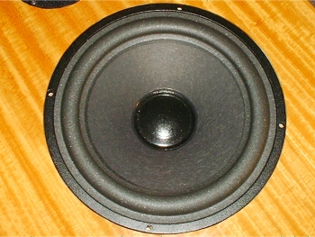 Carefully position the woofer to line up with the fixing holes |
 The woofer has now been screwed down |
The screws should again be screwed loosely to the same position before properly 'biting'. Then they can be tightened in turn - one after the other in rotation. The screws should not be tightened too much - it states in the manual that "There should also be a degree of 'flexibility' between the driver basket and the cabinet." At the same time, the seal must, of course, be a good one.
Finishing and Connecting
The only last thing to do was to short out the necessary terminals at the back of the speakers and connect up to the amplifier.
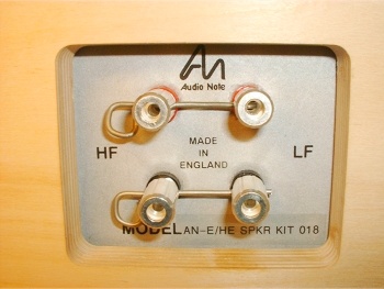
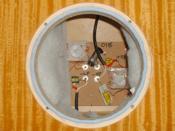
Because of the way that the crossovers and terminal panel are designed, a number of connection topologies are possible. For normal, single run connections, the terminals should be shorted as shown in the picture above. The kit comes with such a set of shorting terminals for just this purpose.
If, however, you intended to bi-wire or bi-amp then you would leave these shorting terminals off and wire the speakers in an alternative manner. The manual shows how to connect them in five different ways.
I connected mine the 'simple' way, using a single stereo pair of speaker cables.
|
|