|
||||||||||||||||||

|
I had already decided that I wanted to create wire looms in this project. One reason for this was that I had not done it for at least 20 years and wanted to see if I could still remember how to. Also, the way shown to manage the wiring in the manual was to wire everything up and tidy up later with tie-wraps - I wasn't too keen on that approach. This of course is a valid approach as it can keep wire lengths to a minimum, but I figured that because I wouldn't be twisting the wires that I would probably make up for that anyway.
Wires that are loomed can be easily manipulated (molded) into different positions; allowing you to loop them over other things that may interfere or be interfered with - a more 3D approach can be taken.
Creating looms meant that I had to plan the wiring in much more detail. Therefore, I created a scaled drawing on the computer using Xara X1 (my favourite vector drawing package). Using the layering feature, I was able to draw various overlays that could be switched on and off at will. I could then also use the drawing's parts to illustrate some things for this site.
This resulted in several looms that will now be discussed in more detail further down this page.
For information about lacing itself, see the Lacing Techniques section.
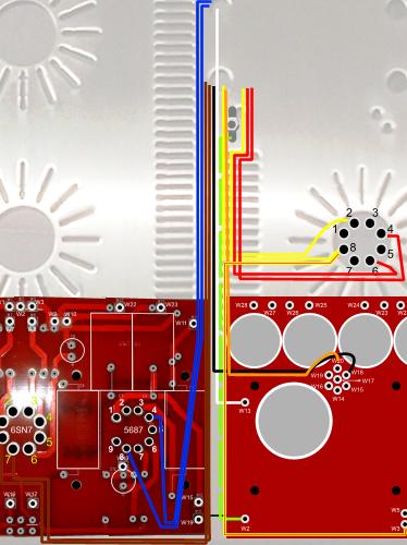
AC Loom 1
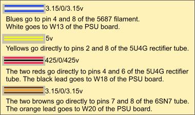
This loom accommodates all but two of the mains secondaries, the chassis earth wire, and the half-wave rectified line from the rectifier valve.
 |
  |
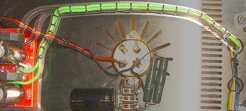
AC Loom 2
This loom accommodates the two mains secondaries (4 wires in all) used for the 300B filaments. These are routed to the filament board where they are rectified and smoothed before going to the 300B's. Once these wires are soldered into place on the filament board, it can then be secured to the chassis. I'm not too keen on the method used to support the board here but it sufficed.
 |
 |
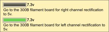 |
300B DC Filament looms
I could have put both sides into a single loom but decided to keep them separate from each other. These sets provide DC from the filament board to the actual filaments within the 300B valves.Here we are looking at the two sets of red/black pairs. I kept both sets exactly the same length as each other.
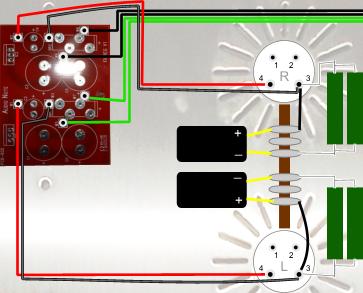
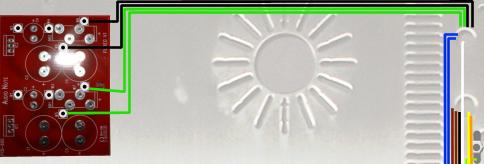
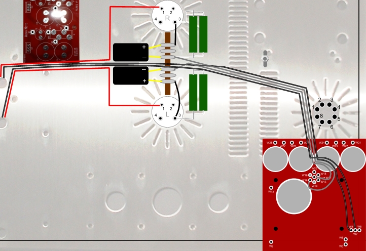
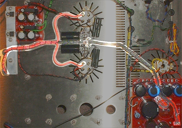
300B O/P transformer and grounding loom
From left to right the 2 sets of the output transformers' primary wires are brought together. The red wires then split off to go to their respective 300B on pin 1. I took care here to keep the wire lengths of each red exactly the same.The two black leads from the transformers continue and join with the ground wires from the tag board. The black primary leads had to be spliced to extension leads because they weren't long enough to make the full journey.
The two black wires from the output transformers' primaries are routed to the 435v line on the PSU board (W7 and W8).
While their red wires go to their respective 300B anode (pin 1).
The grounding wires (shown below in grey) go from the tag board to the PSU boards pins w16 and w17.
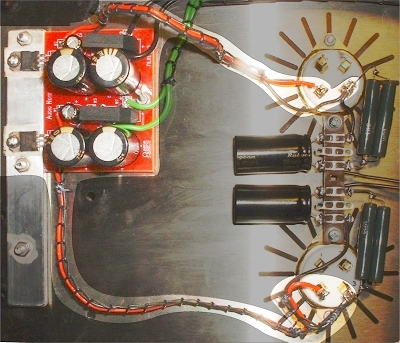
PSU To Driver PCB Loom
This shows the wiring between the PSU Board and the Driver Board.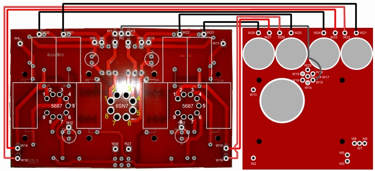
|
|
|
|