|
||||||||||||||||||

|
For me, this is the most exciting part of this project because I had never done this type of construction before.
 |
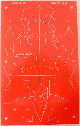 |
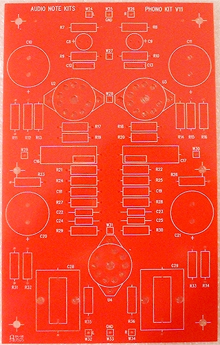
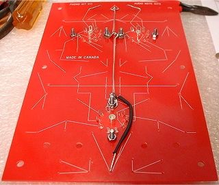
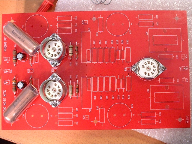
| Here is the unpopulated board from both sides. | |
- Using component legs
- Using silver wire
- Extending component legs with silver wire
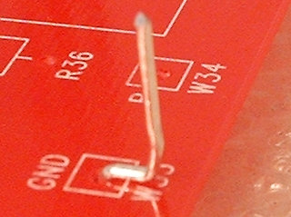
To get maximum connection via surface area, wires should be wrapped around other wires before soldering with silver solder.
This method will always yield superior results to a printed circuit board because rather than there being a very thin layer of copper track providing conductivity, there is instead a significant mass of silver or the uninterrupted tinned copper leads of components. Note that the copper foil capacitors have silver lead-outs which seems identical to the silver wire being used here.
The hardest part of this board is getting started so I will be detailing the start more than anything here. Please bear in mind when watching the video footage, however, that this was a first for me and I do make the odd mistake here and there that I wouldn't now I have the hang of it.
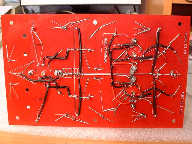
The markings on the underside of the board act as a guide to wiring between the components.
Fitting the Suspended Valve Bases and Central Ground Bus
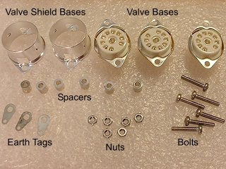
This is where we begin on this board. The valve bases are earthed, via earth tags, to the central ground bus which will be a solid piece of silver wire that will run from one end of the board to the other.
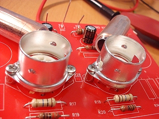
I began by fitting the central valve base. This is the one without a valve shield. All valve bases are held off the surface of the board by metal spacers that sit between the valve base and the board. Through these, bolts are inserted and held on with a nut. One screw of every valve base also has an earth tag fitted before the nut - these should be bent before fitting because the main ground bus wire will be fitted through them later. The earth tag for this valve base should be fitted so that it points in, to the centre of the board.
The other two valve bases also have valve shields fitted onto them. Valve shields come apart into two pieces; the bottom piece must be rested on the top of the valve base before fitting the screws. In the case of these bases, the earth tags were positioned so as to face each other.
When the valve bases are first inserted on their spacers, they will be raised further than they should be and tightening will be required to make them mate. Initial tightening should be done alternately on either side, a little at a time. Tighten using a screw driver rather than tightening the nut. Doing it that way will ensure that the earth tags don't rotate to an undesired position.
Be careful when tightening the valve bases that have valve shields. The shield bases are made from thin aluminium and, as I found on one, tightening too much will cause them to warp as they begin to turn with the bolt. This could be a good place to use a washer, perhaps.
Once the valve bases are in place, it is time to fit the central ground bus. This is a piece of solid silver wire that will run down the centre of the board, from one end to the other, running through all of the earth tags. Each end of the wire will go through a hole and act as a terminal.
I began by passing the silver wire through the two eath tags that are side-by-side - pulling enough through to get to the top of the board and leave enough for a terminal.
The remainder was then cut to the required length and passed through the earth tag on the remaining valve base. From there to the other end of the board is not a straight line so insulation has to be used. Do not go all the way to the terminal position with the insulation as components will need to be wrapped around it at that end later.
Adding Components
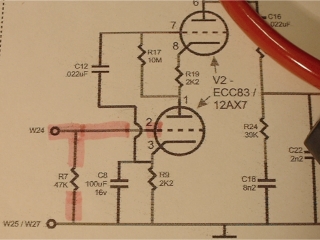
It is advisable to follow the instructions in the manual because on my board there was an misleading guide line on the board brought about by a recent modification made by Andy Grove of AudioNote UK.As I added components to the board, I also marked off the connection on the circuit diagram with a highlight pen so as to make sure that everthing was done correctly.
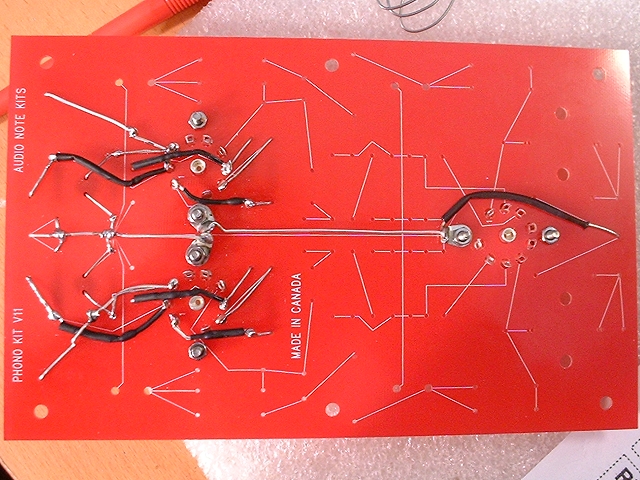
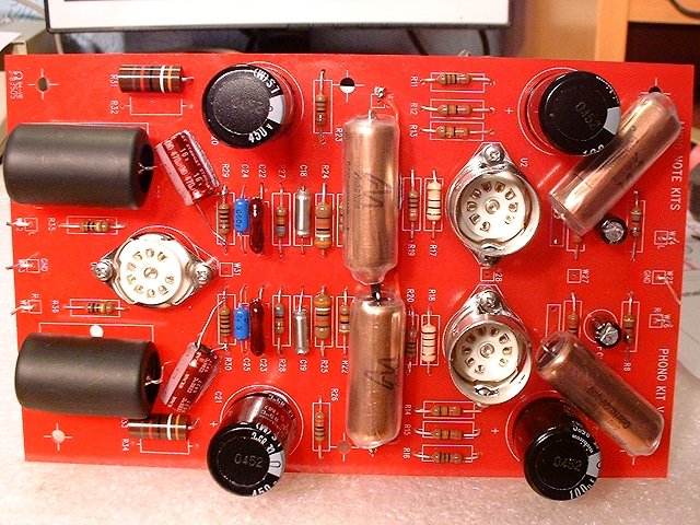
The Completed Board
Call me strange, but I found making this board to be highly enjoyable. You must take your time with it as mistakes would be quite tricky to undo. By the end of it, your wire-wrapping skills will be second to none.
Filament wires have to be fitted as the U2 and U3 valves share the same filament supply and need to be shorted. Leave one set unsoldered as leads from the power supply will be going there later.
The following video is a fly-over of the board. It is intended to show the 3D nature of the wiring (please forgive the terrible tripod panning).
|
|