|
||||||||||||||||||

|
Having now built the M2 power supply board, it was now time to wire it up to the mains transformer's secondary taps and connect the two external regulators.
My first step was to solder ALL wires that eventually attach to the power supply board (including the LED harness). However, it must be noted that some of these (the output leads) need to be insulated against accidental contact with the chassis as these will not be wired in until after the power supply has had a live test. Those wires were looped and their ends individually covered with insulation tape to avoid shorting.
Fitting the Outboard Regulators and Heatsink
The recommended way of fitting the these regulators is to first solder them to the board and later attach them to the heatsink when finally fitting the power supply board.However, I have always done this a little differently by attaching the regulators to the heatsink first, fitting the heatsink, and then soldering the regualtors to the power supply board.
The following video shows this process - the video itself is taken from the build of my DAC Kit 2.1 because it is exactly the same procedure that I used on this occassion also.
The regulators and heatsink in their final position in the L3 Phono Stage Kit
Secondary Wiring
The next job was to connect the secondary windings of the mains transformer to the M2 power supply board. Because I had transplanted the transformer and choke from my old phono stage, it was my intention to simply transplant the loom also. However, it turned out that the distance between the transformer and board in the new unit was greater and therefore it could not be used.Some of the supplied wires had been twisted together so I could not wire using parallel lacing like I normally do - but lace them I did. I started by connecting all the wires to the M2 power supply board and laced back to the mains transformer. The following video is taken from the build of my old phono stage - I have included it because it is exactly the same procedure (except that it is a different distance between the board and transformer and uses untwisted wires).
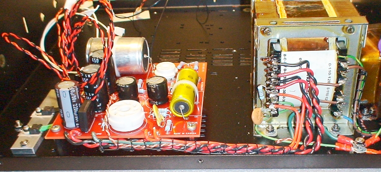
As you can see, not quite as neat as the old phono stage's wiring but that's because of the pre-twisted wires.
Testing the Power Supply
With the secondary connections to the power supply made, I could not switch on and test the voltages to make sure that the power supply was OK.If you connect up the HT and filament output wires as I have, it is important that those wires don't short together or to anything else. To ensure this, it is a good idear to cover their ends with insulation tape.
When switching on for the first time, be ready to switch off immediately if things don't behave as they should (i.e. anything smokes etc). Look at the LED that is connected - it should light up immediately.
Fortunately, everything was OK - I should hope so because this is the third M2 power supply that I have built.
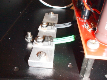
I tested the voltages using probes that I held against the connections to the output wires (rather than the ends of the wires themselves).
The filament voltages came out at 11.7v and 11.8v (expected range is 11.5v to 12v). The HT voltage came out at 263v (expected range being 250v to 300v).
So, all is well with the power supply and I can now move onto the exciting part - building the phono board itself...
|
|