|
||||||||||||||||||

|
 |
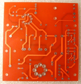 |
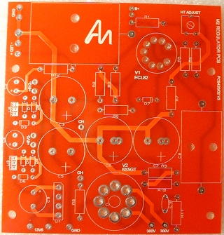
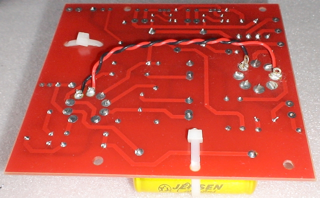
| Here is the unpopulated board from both sides. | |
To me, the M2 power supply board is a quick and easy board to build.
The M2 power supply board supplied with the L3 Phono Stage Kit is slightly different from the ones I have built in the past in two areas:
- Some of the diodes have been replaced by zero-ohm resistors along with different regulators (so the filament supplies are at a different voltage).
- The variable resistor used to adjust the HT voltage has been replaced by two resistors.
The replacement of the variable resistor is welcome because I always thought that they were quite flimsy and therefore too easy to overheat.
The video and some of the pictures and text on this page are actually taken from the previous builds but there is a picture of the finished board from this build at the bottom of the page.
Getting Started
I began by installing the smallest components (i.e. the ones that stand lowest off the board's surface) ending with the 'highest'. This technique allows you to ensure that your components remain flat against the board because when you turn the board over to solder, they lay trapped against the desktop and the board. It also means that larger components don't get in your way as you are populating the board etc.If, however, you are relatively new to board construction then I would recommend sticking with the order and method expressed in the manual - which is pretty good.
I am pretty good at reading resistance values on resistors but, now that I only do it occasionally, I tend to double-check that I have read the colour code correctly. The AudioNote Kits has a good Interactive Resistor Color Code Calculator that I have found useful in the past. The L3 Phono Kit manual does, however, include the colour codes as part if its parts list - making it even easier to get right.
Notes on the valve bases
When soldering the two valve bases, there are two pins on each that should NOT be soldered at this time because they will have A.C. leads from the mains transformer soldered to them later. These are the heater pins.Ensure that they are, and remain, perfectly flushed to the PCB surface.
So that it remains solidly in place, it helps to pull the tags through and bend them over slightly before soldering. This ensures that there is not enough room (or play) for the valve bases, or their pins, to move up or down when replacing valves; hopefully increasing the life of the unit through reduced ware and tare.
Below is some video footage showing the process of fitting the valve bases.
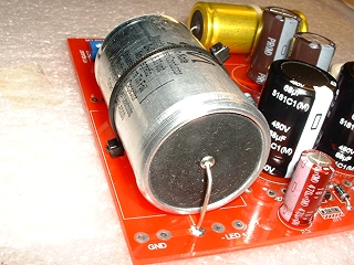
The large capacitors
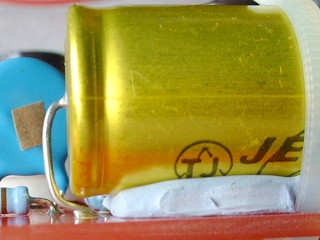
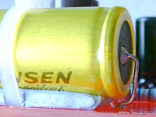
The Jensen capacitor is slightly too long for its position on the board so its leads must be bent under its body. You should, therefore, secure this capacitor in position. To do this, I rested the body on a bed of Blu Tack, which was just thick enough to provide clearance of the leads from the body. Then, I used a tie wrap to secure it. A lead touching the body is not really a problem here because the body is insulated with a covering, but not knowing how much heat will be generated at that position - it's better to be safe. You can see how I managed the clearance in the two pictures below.
|
|
The Audio Note tin capacitor is the largest capacitor. Although the holes for it are the correct distance apart for it, is does have a conductive boady so it is essential to secure it in place so that it will never move and potentially short its body against either of the leadouts.
The filament wiring
The filaments of both the valves on this board share the same AC supply. They are, therefore, joined together; ready to accept the wires from the transformer. These wires use the pins that we left unsoldered previously.The large valve base has two holes in each lug. I used the lower ones for these wires. That way, the top ones remained free to accept the wires from the transformer when we come to wire up between the transformer and M2 board.
The HT Adjust replacement
As I stated earlier, the variable resistor normally used to adjust the HT voltage has been replaced on this kit (and perhaps others?) by two resistors. Below, you can see how I arranged those resistors in place of the pot:
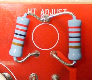
The resistor on the right passes through the top and bottom-right holes. The resistor on the left passes through the bottom-left hole but wraps around the top-most lead of the right resistor.
I'm glad that this has been done because I was never overly impressed by the variable resistors that were used - they always appeared a little flimsy and I always soldered them as quickly as possible because I didn't have much faith in their ability to handle much heat from the soldering iron.
The completed board
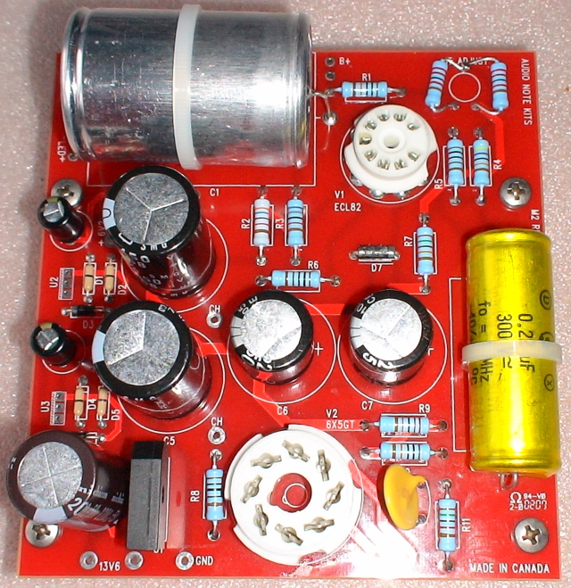
With the board completed, I could now move onto the next stage of fitting and wiring it up.
|
|