|
||||||||||||||||||

|
Digital Power Supply Introduction
The power supply used for the digital board is the same power supply board that is used for the DAC Kit 1.1. The difference is that here, it is only used to power the digital board - while the DAC Kit 1.1 uses it to power both digital and analog sections.
|
|
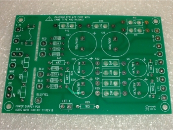
This is the simplest of boards to construct. ALL taps from its mains transformer go directly to the board and regionalization is taken care of by a combination of jumpers on the board itself. The board also holds a mains fuse and has its own mains switch on the back panel that is independent from the mains switch for the analog section.
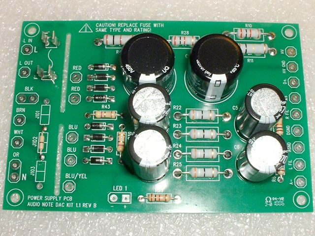
The completed board is shown below:
Please note that the jumper in position J102 may be different for different parts of the world - it determines which taps are used from the mains transformer's primary windings. Mine is configured for 240v (UK) operation.
Wiring the Digital Power Supply
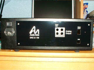
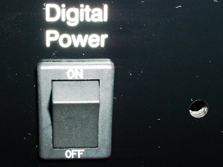
Before we can fully wire the digital power supply, the rear panel has to be fitted. This is because the digital supply's mains switch and LED have to be mounted in position so they can be wired correctly.
|
|
The above pictures do not do justice to the rear panel because it is so reflective. The rocker switch was a nice, reassuringly tight fit. The hole to the right of the rocker switch is where the digital power supply's LED will fitted shortly.
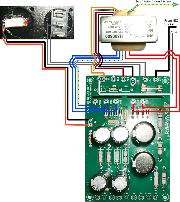
The diagram above shows the mains related wiring for this board. The wiring is actually not as complex as is looks because all wires from the transformer to the board are colour-coded and each corresponding colour is printed on the board itself. You just have to make sure that you don't mix up any of the many black and white wires.
In fact, the only reason for drawing it here is because I wanted to plan out my looms (which you would probably not do anyway). The diagrams in the manual are more than adequate for normal wiring purposes.
So, the first thing I did was to glue the LED harness to the rear panel and solder some leads to the rocker switch.
I then began the first loom, which included the black and white wires from the IEC socket along with the two red secondary wires from the transformer.
Next was a loom from the rocker switch and LED wires that met up with the primary wires and then the blue and blue/yellow leads from the secondary.
Finally I loomed across the top of the board.
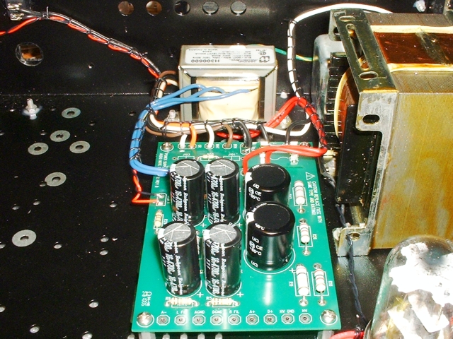
Above, you can see the finished result. The whole assembly will gladly hinge which will make it very easy to connect the power supply output wires at the bottom of the board at a later stage.
Finally all that is now required is to test the digital power supply. This is simple as it has its own mains rocker switch. Once switched on, there are just a couple of voltages to check and the digital board's power supply is ready for operation.
|
|