|
||||||||||||||||||

|
Installing the I/V Transformers
I decided to fit the I/V transformers before fitting the digital board. This gave me the chance to connect them up to the analog board's input while I had a little space to spare.The I/V transformers sit on top of spacing pillars so they need to be fitted first.
The I/V transformers themselves are contained in metal canisters. Plastic grips, like those you find holding large capacitors, are used to hold the canisters so they can be screwed onto the spacing pillars.
One side of the I/V transformers can now be connected to the analog board. 3 wires per channel are used (blue, green, and yellow). The blue and green wires are connected together and each pair are connected to the central earth bus on the analog board. The yellow wires are connected to terminals W41 and W43.
The digital board can now be fitted.
Digital Board Overview
I went for the Signature Digital Board. This has the addition of PK Black Gate capacitors (a total of 12 in fact), tantalum resistors in analog signal areas, and an Audio Note Digital Interface Transformer.I believe that all the digital boards supplied with this kit (both standard and signature versions) have their analog filter removed as per all recent Audio Note DAC's.
The board also came with the components necessary to interface with the I/V transformers. I assume that level A kits would come with a different configuration here (mine is a level B meaning that it uses I/V transformers).
Normally (at least in the DAC Kit 1.1), the board comes with an XLR connector fitted to the board that acts as an optional 110ohm switchable input. However, this was left off on my board. This is probably due to the fact that I went for the additional USB option. In this case, the extra connection is, instead, used for connecting to the USB board - more on that later.
The digital board also came fitted with a coax cable fitted to its primary input connectors. Whether this is standard or not, I don't know but I have been told that it yields a significantly better signal using coax than normal twisted pair wires.
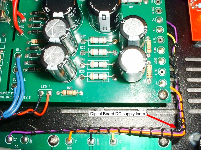
Power Supply Wiring
Wiring up the Digital board to the digital power supply couldn't be easier. You just have to connect up five wires that connect to pads that are labelled with the same identifier on both the digital board and its power supply board. Simple.
Finishing the I/V Transformer Connections
The other side of the I/V transformers can now be connected to the digital board. Again, we have 3 wires per channel to connect; 2 go to ground (green and black)and one to signal (red). Unlike at the analog board, the grounds are connected to seperate pads on the digital board.
|
|