|
||||||||||||||||||

|
As with all the other boards (except the filament board which is too cramped), I decided to use PCB pins for the interconnect wires. The pins were the first things to be fitted - they fit snugly and require pushing gently in with pliers. I prefer pins because the soldering of terminal wires can be done without disturbing the board itself; possibly putting strain on the wiring etc. and so long as the leads touch the circuit board pads then I can't see any problem with the approach as the holes are plated through and some of the silver solder will penetrate through. The pins, once pushed through, can be soldered from behind.
This board, like the driver board, accepts components on both sides. Here, all the resistors are surface mounted onto solder pads rather than going through holes. Because tantalum resistors were used, they were bigger than the ones illustrated in the manual and so ended up being higher up because I wanted to get as much surface contact between the leads and pads. Having the resistors off the board is also a good idea for cooling but make sure they are not too high because that side of the board will eventually be resting very close to the chassis once the board is fitted (you MUST maintain a gap between the components and the chassis otherwise heat will conduct to a specific point and the component will be bound to fail).
TIP: I used Blu-Tack to secure the resistors in place while soldering. This gave more than enough stability and security to allow soldering in a single step (rather than tinning and tag-soldering as the manual suggested). However, you will have to ensure that your lead bending is done accurately to ensure good surface contacts to begin with. It may also help to keep the leads long until after soldering so that something heavy may be placed on the end being soldered (if it is slightly raised above the board).
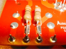 Surface mounted tantalums - taking advantage of some pins. |
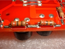 Some more surface mounted tantalums. |
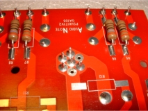 A group of pins that will be used as a common 0v point later in the wiring. |
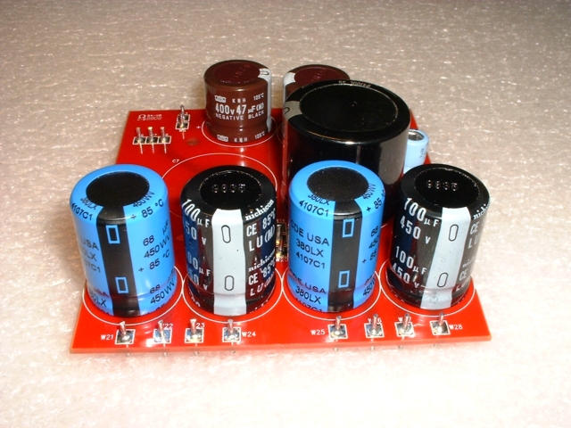
Fitting the capacitors was, of course, easy. Just remember to fit them the correct way around (they are all polarised except for one). If you fit any the wrong way around then you can probably expect it to blow when you first switch on (and you don't want that to happen!).
+++
I obsessively clean my solder joints as I go along using stiff brushes and isoproponol [RS INFO] ++ Link
to dedicated section showing dispenser, brushes and a little on techniques etc.
+++
|
|