|
||||||||||||||||||

|
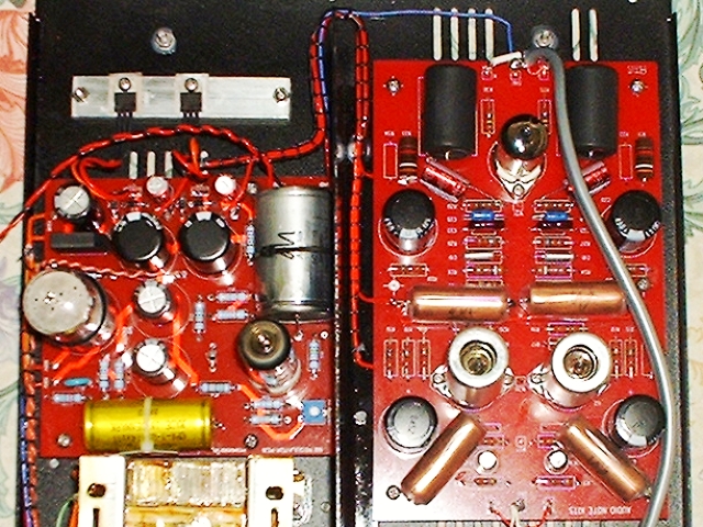
Now that the phono board is complete, there are just a few things to complete the kit.
Please note that I will not be going into the details of the rear connections or back panel. This is because I decided before the start to do a modification of my own to allow a second source to be switchable at the output.
Fitting the Screen
First the screen was fitted. This is a sheet of metal that sits between the power supply and the phono board, acting as an electromagnetic screen between the two.
Supply Wiring
Next up is wiring the power supply to the phono board. This is pretty straightforward. The leads have to go around the screen although it would be possible to drill a hole through the screen for the shortest possible path if you felt so inclined.
It is at this stage that I made the final connections to filaments of the valves.
Wiring the Back Panel
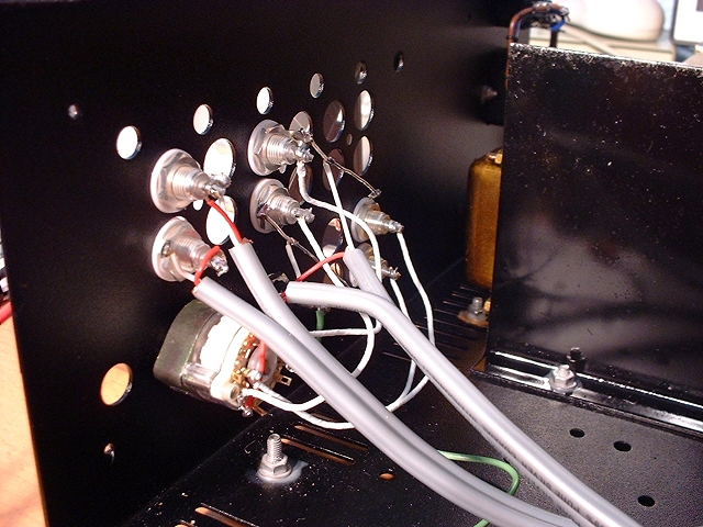
The back panel signal connectors consist of an input pair and output pair of RCA connectors. These are connected to the two ends of the phono board.Please note, however, that I included a third pair of RCA connectors and an Elna switch to enable me to switch between DAC and phono from the back panel. Why? Because I only have two very short AN-V cables and this was the best way to arrange everything for my own particular circumstances and environment.
In view of this, the following picture is not typical of the back panel. In addition, the back panel cover needs to be modified (not shown).
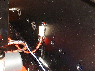
Now all we have to do is fit the front panel which is held on with four screws, nuts, and spring washers then fit the LED into place. There is also an Audio Note logo sticker to be fitted; I fitted mine above the LED hole.
The LED's legs pass through a plastic connector; therefore its leads can be bent so that the LED can fit into the hole in the front panel and the plastic body, acting as a support, can be glued onto the front plate.
Final Voltage Adjustment
Now that everything is connected, it seemed a good idea to check that HT voltage before fitting the lid. I adjusted it and left the probes connected to monitor that voltage over time. It did fluctuate so I did the final adjustment to 260v after about 20 minutes.Once this was done, it was time to fit the lid. The lid is held on with no less than 10 countersunk screws and makes that whole assembly extremely sturdy.
Switching On and playing the First Record
I was pretty confident that everything was as it should be but this is still the most nervy time of a build; will it work? Yes it did!The first thing I checked for was the presence of any hum - no, none there at all. That means one of two things - either it is a good design and build or it aint working. So, only one thing for it - put a record on.
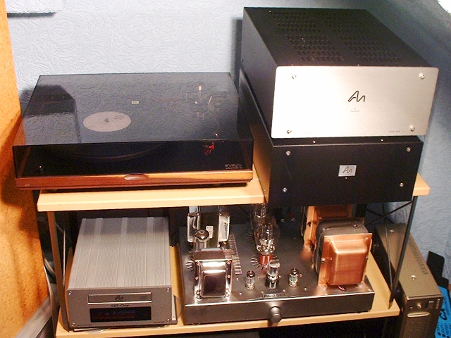
Music, sweet music!
Now it's time to play lots of music...
|
|