|
||||||||||||||||||

|
Now for the exciting part - the phono board build!
Firstly, I must say that this board is the best hard-wired board that I have ever seen. All component holes (including the valve base holes) are plated through. Also, the earth, HT paths, and parallel filaments actually have PCB tracks laid down - very wide ones. This is quite interesting; even if you wanted to bypass these tracks, they are a very good guide as to where their locations are (especially the earth trace).
Another great thing about this board is that the components are marked below the board as well as above - this is really useful as you are constantly having to turn the board over.
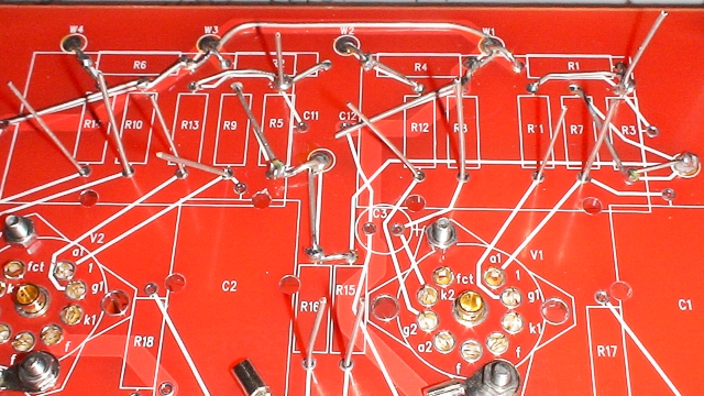
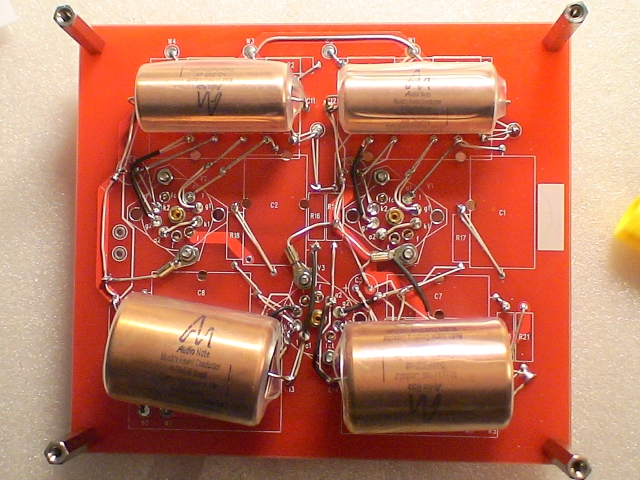
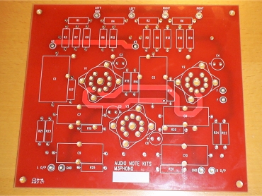 The board's top side |
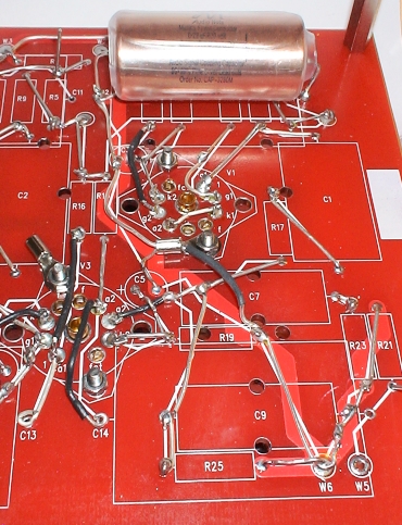
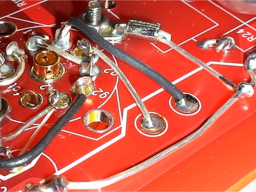
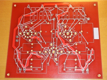 The board's underside showing component connections |
Another significant thing about this board is that there will be four large capacitors mounted from the underside of the board.
For those unfamiliar with hard-wired boards, these use either the component legs or extensions of them using silver wire to make the connections between each other. This is unlike printed circuit boards that tend to compromise conductivity by using thin copper tracks. Once finished, they look just like printed circuit boards from the top.
This board shows all the connections that are to be made on the reverse in the form of lines that show the necessary connections that are to be made between components. It is always advised, however, that you double check each connection on the circuit diagram before finalising it. In the past, I have always torn out the circuit diagram from the back of the manual and highlighted each connection with a highlighter pen so that I knew when the circuit was complete. With this kit, a separate diagram AND a highlighter pen have been included (must have stolen my idea).
Hard wired boards will always be more difficult to build than a PCB equivalent but I find them good fun to build and they will always be electrically superior.
Fitting the valve bases
|
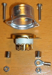
This is an exploded view of one of the three valve base assemblies.
At the top is the base of a spring-loaded valve shield that will be fitted over the valve once inserted. That sits on top of the valve base itself, which is supported by two column spacers.
|
Populating the board
Before starting on the components, I fitted the board spacers to the underside of the board. These are 4cm high - they need to be high because of the large capacitors that will eventually be mounted under the board. The long spacers are great because they allow the board to be stand upright; even with component legs sticking through.One confession I have is that I decided not to follow the instructions for assembling the board - instead I decided to improvise. I will still be following the guides printed on the underside of the board but I decided to start at the input and work my way to the output.
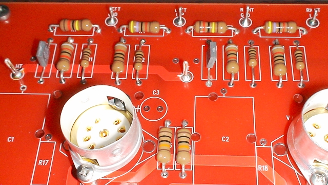
The following pictures show the first two components being inserted and wired up:
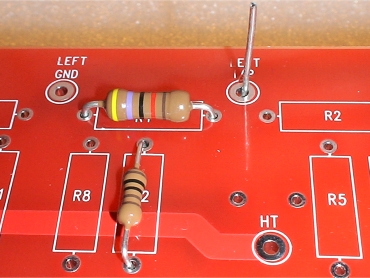 This shows the first two components in place |
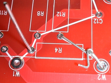 The leg of R12 is wrapped around the leg of R4. R4's leg is then inserted through W2 to form the signal input terminal |
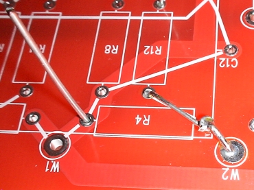 Finally R12's leg is clipped and the legs are soldered |
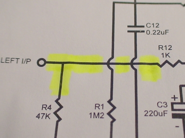 Progress is marked on the circuit diagram - so we can see that R4 and R12 have been connected to the input terminal |
I then decided to do exactly the same for the right channel. You have to bear in mind that eventually a large capacitor will be mounted over these connections on the underside, so they must lie as flat as possible here.
After about an hour, the board looked like this:
Note that the wiring needn't be quite as complicated as this because you could rely on the earth and HT tracks that are already there for many connections, but I have recreated those tracks too.
Now it is just a matter of carrying on in the same way until the circuit is complete.
It is also quite surprising how much easier it is to work on this board with it having the component layout printed on the bottom as well as the top - without them you would have to continually turn the board back and forth to make sure where you are. What also makes it easier is the earth and HT tracks - although I am effectively reproducing them, they are still a great help for figuring out where you are in the circuit.
Here are a series of pictures taken about an hour later. Here, all the components on the topside have been inserted. The main ground paths have still to be sorted as well as the insertion of the 4 large underside capacitors.
Please click on any of the following images to view an enlarged picture:
)
|
)
|
)
|
)
|
)
|
)
|
)
|
)
|
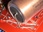
Fitting underside capacitors
It is important that the areas where the large underside capacitors are to be mounted are left as flat as possible. This is especially true of the ones at the output side of the board because they are rather large and don't leave a huge amount of clearance between themselves, the board, and the chassis. Fortunately, the large capacitors have been covered with clear, and rather thick heatshrink so there is very little danger of their copper bodies shorting out to anything. Still though, make sure that no sharp wires can penetrate.Like the copper capacitors that are mounted on the top of the board, they should be inserted in a particular direction. Which direction is described in the manual. Although these are not electrolytics, they are still said to be directional to a certain degree.
|
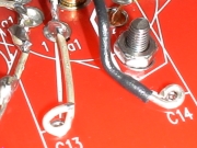
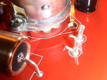
I began with the capacitor shown opposite. Now that this was in place, I could begin to wire the ground wire for that side of the board.
Note that you don't strictly have to take a ground wire all the way down like I have done because the board actually has a ground track on it - but I did nevertheless. You can follow the ground path from the left lead-out of the capacitor - it takes the same trail as the earth track - deviating slightly to go through the earth tag that is attached to the valve base. |
|
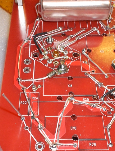
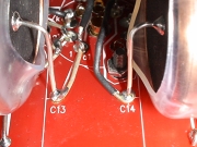
I then did the same with the equivalent capacitor on the opposite side of the rear of the board (i.e. the other channel).
Again, you can follow the ground path from the left lead-out of the capacitor. |
Next up were the remaining 2 large copper capacitors:
|
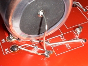
I had already left 2 loops of wire for these capacitors to be inserted at the cantre of the board. Once inserted through these, I folded the inserted wire over slightly on the top of the board and soldered in place. I then tightened the loops and soldered those also.
|
|
|
The outer legs of each of these capacitors weren't passed through their respective holes. Instead, they were anchored by the leads from R21 and R22 (respectively) by passing them under them and wrapping slightly and then passing through the output terminal holes (W5 and W8) to make the output terminals.
|
|
Preparing the filament terminals
There are two filament supplies coming from the power supply and three valves on the phono board. The first is shared between the two first stage valves. The second stage valve has its own.With the first stage valves, you would normally connect between them using a twisted pair of wires. However, this board provides substantial tracks that join these together. I decided to rely on these tracks for this purpose. So I only needed to provide a connection to one of these. I decided to use some silver wire to create two topside terminals to connect this filament supply.
 Some silver wire connects one to set of filament pins and passes through to make terminals on the top of the board |
 I formed bent over the terminals for added support |
One important note is that if you are going to rely on the filament tracks, remember to solder the filament pins on the 'other' valve of the pair!
First stage testing
The manual contains three blocks of simple resistance checks that can easily be performed to make sure that most of the critical connections are correct.Most of these are between certain pins of the three valves to earth and other components. One thing I did notice was that because they are in-circuit, you do tend to get floating resistance values (i.e. values start to climb or reduce slowly) because of capacitors charging etc. so usually your first reading is the most correct. All readings were fine!
I thoroughly enjoyed the building of this board. Having the component markings below the board helps tremendously. The pre-defined tracks also help - whether you want to rely on them or not. I have effectively duplicated the grounding tracks but am going to rely on the HT and filament tracks as these are just straigtforward DC voltages.
The next stage is to hook-up the power supply and do some more testing.
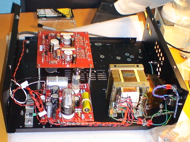
Now in its rightful place inside the chassis awaiting hook-up and testing
|
|