|
||||||||||||||||||

|
Please note that because the M2 power supply board was also used in the Kit1 Phono Stage (built elsewhere on this site), I am re-using many of the pictures and videos from that build on this page. This has allowed me to build the board much faster than I would have if I'd had to take all the pictures and video all over again.
 |
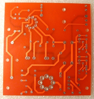 |
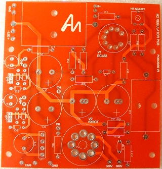
| Here is the unpopulated board from both sides. | |
I began with the smallest components (i.e. the ones that stand lowest off the board's surface) ending with the 'highest'. This technique allows you to ensure that your components remain flat against the board and also means that larger components don't get in your way as you are populating the board etc.
If, however, you are relatively new to board construction then I would recommend sticking with the order and method expressed in the manual - which is pretty good.
I am pretty good on reading resistance values on resistors but, now that I only do it occasionally, even I tend to double-check that I have read the colour code correctly. The manual pointed me toward an Interactive Resistor Color Code Calculator on the AudioNote Kits website - I found this to be really useful during this build. It is a 5-band calculator that allows you to either click on the colours OR select the most common tantalum resistor values from a combo box and let it show you the correct colours from that.
Notes on the valve bases
When soldering the two valve bases, there are two pins on each that should NOT be soldered at this time because they will have A.C. leads from the mains transformer soldered to them later. These are the heater pins.Ensure that they are, and remain, perfectly flushed to the PCB surface.
So that it remains solidly in place, it helps to pull the tags through and bend them over slightly before soldering. This ensures that there is not enough room (or play) for the valve bases, or their pins, to move up or down when replacing valves; hopefully increasing the life of the unit through reduced ware and tare.
Below is some video footage showing the process of fitting the valve bases.
The large capacitors
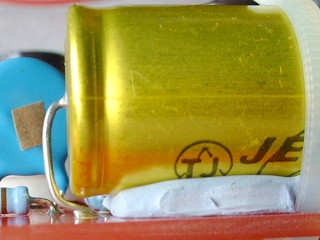
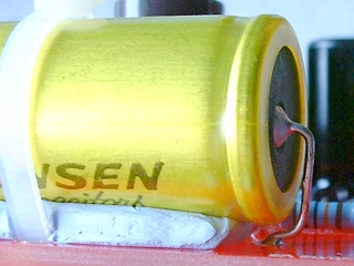
The Jensen capacitor is slightly too long for its position on the board so its leads must be bent under its body. You should, therefore, secure this capacitor in position. To do this, I rested the body on a bed of Blu Tack, which was just thick enough to provide clearance of the leads from the body. Then, I used a tie wrap to secure it. A lead touching the body is not really a problem here because the body is insulated with a covering, but not knowing how much heat will be generated at that position - it's better to be safe. You can see how I managed the clearance in the two pictures below.
|
|
For the remaining large capacitor, the phono kit used an Audio Note tin capacitor. This kit, however, replaces that with a Multicap. This is much smaller and more manageable than the tin one. In fact, you could probably get away with not securing it with tie-wraps - I did though.
The filament wiring
The filaments of both the valves on this board share the same AC supply. They are, therefore, joined together; ready to accept the wires from the transformer. These wires use the pins that we left unsoldered previously. Lacing the wires meant that the leads could be permanently moved (bent) into a position away from the surface of the board to avoid shorts - no floppy wires there.The large valve base has two holes in each lug. I used the lower ones for these wires. That way, the top ones remain free to accept the wires from the transformer when we come to wire up between the transformer and M2 board.

The completed board
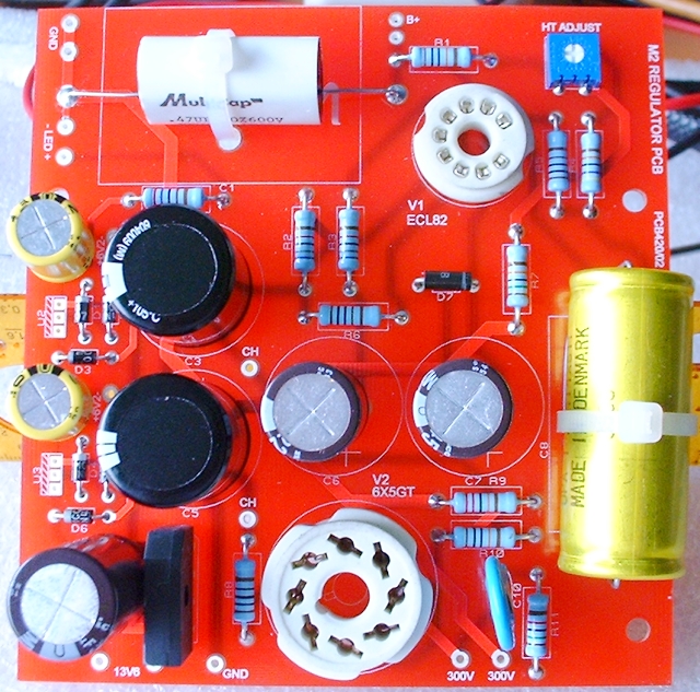
One thing to note from experience is that when soldering the pot (variable resistor) shown in the top right-hand corner, you should make sure you solder the legs quickly because too much heat can easily damage these delicate devices. Also, the leads only protrude a very small amount through the holes - I pulled them through (very gently) and bent them over a little. I also made sure that they were securely soldered on both sides (again be quick). It also helps to set the position away from the side being soldered to avoid excessive heat build-up in one particular area of the track - I made sure it was set to the centre position.
So, this board was very straightforward to construct and shouldn't present any real problems.
|
|