|
||||||||||||||||||

|
Beginning the Build
It is always a good idea to start off by checking all of your kit bags against the checklists that come with them. This serves two purposes - firstly, it makes sure that nothing is missing and secondly, it familiarizes you with all the components that you will be using.This page covers the very first part of the construction up to our first wiring job.
The first thing is to attach the feet to the chassis. I won't go into any depth on this as it is such a simple task - just don't tighten them too tightly as the feet are only rubber. I also used some nail varnish on the nuts (inside the chassis).
Note: It must be remembered that this kit has two separate power supplies - each one having its own mains transformer and switch!
The M2 power supply is responsible for powering the analog output. The other power supply (which I will call the 'digital' power supply) is responsible for powering the digital board.
Using the Correct Solder
Whenever I start an audio project, it is time to bring out the audio grade silver solder. I always use Audio Note silver solder myself which I purchase from the Hi-Fi Collective website here in the UK. A 5 meter length costs around £10 (10 British pounds) and will normally last me about two kit projects.
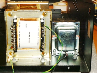
Fitting the M2 Mains Transformer and Choke
In addition to a mains transformer, the M2 power supply also uses a significantly sized choke to provide additional smoothing.Fitting these into the chassis is easy. Getting the nuts onto the rear-most screws of the choke is a little tricky because of its proximity to the rear of the chassis; but this is no showstopper.
These are both held on by four screws, lock washers, and nuts.
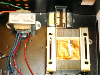
Fitting the 'Digital' Power Supply Mains Transformer
The digital board's mains transformer was next. Again, this was no problem at all. Two screws, locking washers, and nuts hold it on.
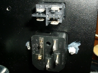
Fitting the Rocker Switch and IEC Socket
This is the first of two mains rocker switches that are used in this kit (the other is dealt with much later in the build). It simply snaps into position on the rear of the chassis.The IEC socket is attached using two small screws, lock washers, and nuts.
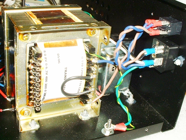
Initial Mains Wiring
Our first wiring job is to wire the mains input to the primary windings of the M2 power supply's transformer via the rocker switch.A number of pre-made cables are supplied to make this as easy as possible. It is important to note that other wires come from the IEC socket that will 'eventually' go to the digital board's power supply PCB. These were provided with heat shrink insulation on them so they can be left to one side until later without danger of shorting to anything.
Normally, I would scrap the pre-made cables and wire the mains from scratch; soldering all the connections. However, on this occasion, I decided to use the cables provided (it was the hottest day of the year so far - too hot to think).
The manual shows each stage of the mains wiring using some easy-to-follow diagrams. The main diagrams are for 120v (North American) operation but there is also a look-up table of diagrams for all other country-specific wiring. The idea is that if you live in a different country then you would select the relevant diagram that would then replace one of the other steps. I use 240v (UK) wiring and found this to be a good method.
|
|